.jpg?format=pjpeg&width=1600&quality=75&auto=webp)
ELECTRICAL POWERHOUSE MATERIAL FIT FOR HIGH VOLTAGE
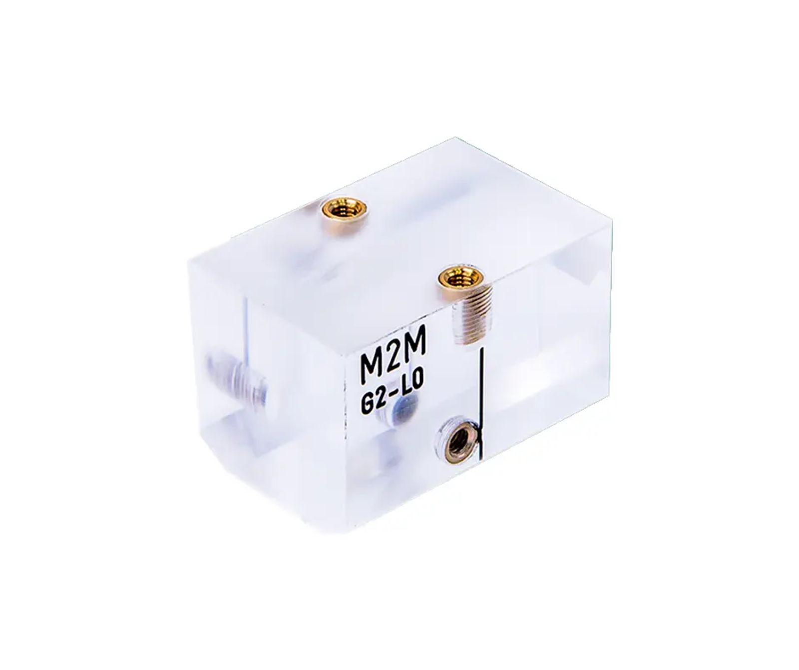
Rexolite® is a rigid, cross-linked polystyrene widely used for precision components that demand a stable, low-loss dielectric and excellent acoustic transmission. Engineers in RF and microwave, high-voltage electronics, radar and sonar, and acoustic imaging choose Rexolite® for its combination of predictable electrical properties, low moisture absorption, and clarity that supports both signal integrity and sound propagation
Rexolite Material Properties
Rexolite® is a cross-linked polystyrene plastic known for its excellent electrical and acoustic performance in demanding environments. The material has the following benefits:
- Very low dielectric constant and dissipation factor support stable RF and microwave performance across a wide frequency range.
- High radiation resistance and good dimensional stability make it suitable for aerospace, defense, and high-energy applications.
- Excellent acoustic transmission and clarity enable use in sonar lenses, acoustic windows, and underwater transducers.
- Low moisture absorption helps maintain consistent electrical and mechanical properties over time.
Property | Typical Value | Notes |
|---|---|---|
Density | 1.05 g/cm³ | Rexolite® 1422 unfilled. |
Dielectric constant | 2.53 | Stable up to 500 GHz. |
Dissipation factor | 0.00012 at 1 MHz | Very low dielectric loss. |
Operating temperature | -60 to +100 °C | Recommended continuous range. |
Acoustic impedance | 2.5 MRayl (approx.) | Suited for sonar/acoustic lenses. |
Water absorption (24 hr) | 0.08% | Very low moisture uptake. |
Dielectric strength | 500 V/mil (1/8" thick) | High electrical insulating capability. |
Rexolite® offers good resistance to many common process chemicals used in electrical and RF environments.
Resistant to: alkalis, alcohols, aliphatic hydrocarbons, and most mineral acids.
Not recommended for: aromatic solvents, which can attack or degrade the material over time.
Applications
Rexolite® is widely used across RF, microwave, and acoustic systems where low-loss dielectric performance and sound transmission are critical.
- Microwave components for high-frequency signal routing and coupling.
- Antennas and RF lenses for radar and satellite communication systems.
- Sonar lenses and acoustic windows in underwater imaging and transducer assemblies.
- Radar windows and radomes requiring stable electrical properties and environmental durability.
- High-voltage insulators and spacers in power supplies and test equipment.
- RF and microwave test fixtures, jigs, and precision dielectric standards.
Machinability
Rexolite® also offers good machinability, allowing tight-tolerance parts and fine features for complex OEM designs for RF, microwave, and acoustic systems.
- Can be precision machined into lenses, waveguides, insulators, and custom RF components.
- Maintains smooth surfaces and optical-quality finishes with proper tooling and process controls.
- Supports the full range of volumes, from one-off prototypes and engineering samples through short runs and ongoing production for OEM programs.
- Holds tight-tolerance features on Rexolite® components, often down to a few thousandths of an inch on critical dimensions such as interfaces, bores, and mounting features.
- Produces fine details and small features appropriate for complex RF and acoustic geometries while maintaining surface quality
Rexolite® is best treated as a precision dielectric and acoustic material first and a structural plastic second. For these reasons, design choices around wall thickness, tolerances, and comparisons to PTFE or acrylic should reflect that priority. Engineers can engage early for design-for-manufacturing guidance, prototype support, and scalable production of Rexolite® parts that meet strict electrical and acoustic performance requirements.
Design Tips & Considerations
Wall Thickness & Part Geometry
- Favor uniform wall thickness wherever possible to minimize internal stress and warpage during machining.
- Avoid very thin, unsupported walls on large parts. Use ribs, fillets, and gradual transitions instead of sharp corners to reduce cracking risk.
- For acoustic or RF lenses, keep transitions smooth and avoid abrupt section changes that can introduce reflections or local stress concentrations.
Tolerance & Surface Finish Expectations
- Set realistic tolerances based on part size. Tight features (bores, interfaces) can often be held to a few thousandths of an inch, but global flatness and parallelism should be looser on larger parts.
- Specify RF-critical surfaces explicitly so they can be machined and finished with appropriate tooling and feeds.
- Avoid over-constraining dimensions that do not affect electrical or acoustic performance. This keeps cost and scrap under control.
Common Rexolite Machining Pitfalls & How To Avoid Them
Rexolite® is a relatively easy-to-machine, rigid dielectric material, but it behaves differently from metals or tougher engineering plastics. Process control is critical to avoid chatter, surface defects, and stress-related failures.
Chatter & Dimensional Instability
- Pitfall: Chatter on thin walls, long features, or lightly supported parts can leave poor surface finish and shift critical RF or optical dimensions
- Prevention:
- Use sharp, positive-rake carbide tools and conservative step-downs to reduce cutting forces.
- Optimize fixturing with full support under thin sections and minimize tool overhang to improve rigidity.
- Adjust spindle speed and feed to keep a consistent chip load and avoid dwelling in the cut.
Polishing & Surface Finish
- Pitfall: Over-aggressive polishing or incorrect abrasives can round edges, change optical curvature, or leave micro-scratches that impact RF and acoustic performance.
- Prevention:
- Define critical surfaces (lenses, RF interfaces, sealing faces) and apply controlled multi-step finishing only where needed.
- Use fine-grit abrasives and progressively finer compounds, checking geometry against drawings during the process.
- Avoid excessive localized pressure or heat during polishing to prevent distortion or surface haze.
Crazing, Cracking, & Heat Management
- Pitfall: Crazing or micro-cracking can occur if Rexolite® is machined with dull tools, excessive heat, or aggressive coolants and solvents.
- Prevention:
- Maintain sharp tooling, light cuts, and proper chip evacuation to keep cutting temperatures low.
- Use air blast or compatible coolants. Avoid aggressive solvents that can attack the material.
- Design toolpaths to minimize re-cutting chips and reduce rubbing, which generates unnecessary heat.
Holding Tight Tolerances Without Over-Stressing The Part
- Pitfall: Forcing parts in fixtures or chasing unnecessary micron-level tolerances can introduce internal stress that shows up later as warp or dimensional drift.
- Prevention:
- Use conformal soft jaws or vacuum fixtures where appropriate to distribute clamping loads.
- Focus tight tolerances on function-critical features and keep non-critical dimensions more forgiving.
- Allow parts to relax between roughing and finishing operations on large or complex geometries.
Protecting Optical & RF-Critical Features
- Pitfall: Handling and secondary operations can nick edges, scratch surfaces, or contaminate RF and optical features.
- Prevention:
- Mask or protect finished critical areas during subsequent machining steps.
- Use clean, lint-free handling practices and dedicated packaging for finished Rexolite® components.
- Inspect critical features under appropriate lighting or metrology (e.g., optical comparators, profilometry) before shipment.
Rexolite Vs Other Materials
When To Use Rexolite® Vs PTFE
- Choose Rexolite® instead of PTFE when you need better rigidity, dimensional stability, and easier machining while still maintaining a low dielectric constant and low loss.
- Use PTFE when extreme chemical resistance, very low friction, or operation well beyond Rexolite’s recommended temperature range is more important than stiffness and machinability.
- For RF fixtures and lenses that must hold shape over time, Rexolite® is generally a better structural dielectric than PTFE.
When To Use Rexolite® Vs Acrylic
- Choose Rexolite® over acrylic when dielectric performance, radiation resistance, and dimensional stability under load are critical, especially in RF, microwave, or high-voltage environments
- Use acrylic when you primarily need high optical clarity for visible light, moderate mechanical loads, and cosmetic transparency with less emphasis on RF or high-voltage behavior.
- For sonar lenses and acoustic windows, Rexolite® is often preferred because of its acoustic impedance and dielectric properties, even if acrylic may appear similarly clear.
Material | Key Strengths | Where Rexolite® Wins |
|---|---|---|
Rexolite® | Low dielectric constant, low loss, good radiation resistance, excellent acoustic transmission | RF/microwave components needing stable dielectric properties and sound transmission. |
High optical clarity, low cost | Rexolite® is better for high-voltage, RF, and radiation-exposed parts. | |
Excellent chemical resistance, very low friction | Rexolite® offers better rigidity and dimensional stability, with less weight than PTFE in many cases. |
Practical DFM Checklist For Engineers
- Confirm operating frequency, voltage, temperature, and environment first, then validate that Rexolite®’s dielectric constant, loss, and temperature range meet those needs.
- Share any extreme mechanical or thermal loads early. If the part must act as a structural member or see high heat, consider whether another plastic or a hybrid design is more appropriate.
- Involve your machining partner during concept or prototype stage to refine wall thickness, tolerances, and fixturing approaches specific to Rexolite®